What compression ratio actually changes on a race engine
Compression ratio controls how hard a motorcycle engine pulls, how much heat it makes, and how close it runs to detonation. On a modern 450cc motocross single, moving from 12.5:1 to 13.5:1 is typically worth two to four percent in torque across the working RPM band. Most of that gain shows up in the midrange, where the engine spends its time between corners — not at the rev limiter.
The cost side is shorter component life and a thinner knock margin. Higher cylinder pressure loads bearings and rings harder, and it raises chamber surface temperatures. A ratio that survives a 20-minute moto on race fuel can fail on pump gasoline in a 40-minute endurance stage. That is why we set the ratio after we know the fuel, the moto length, and the ambient conditions — the chamber gets machined last and decided first.
Cam timing sits in the same equation. A long-duration cam bleeds cylinder pressure at low RPM, so an engine with aggressive cam timing needs a higher static ratio just to keep its low-end response. Change one without the other and you get an engine that looks better on the dyno sheet than it laps.
Squish band: the few millimeters that control combustion speed
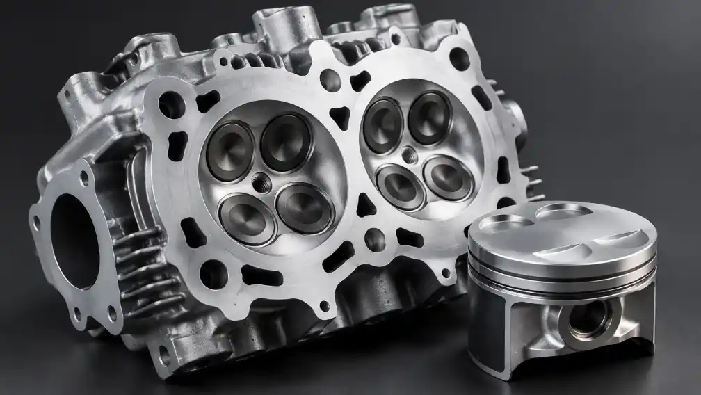
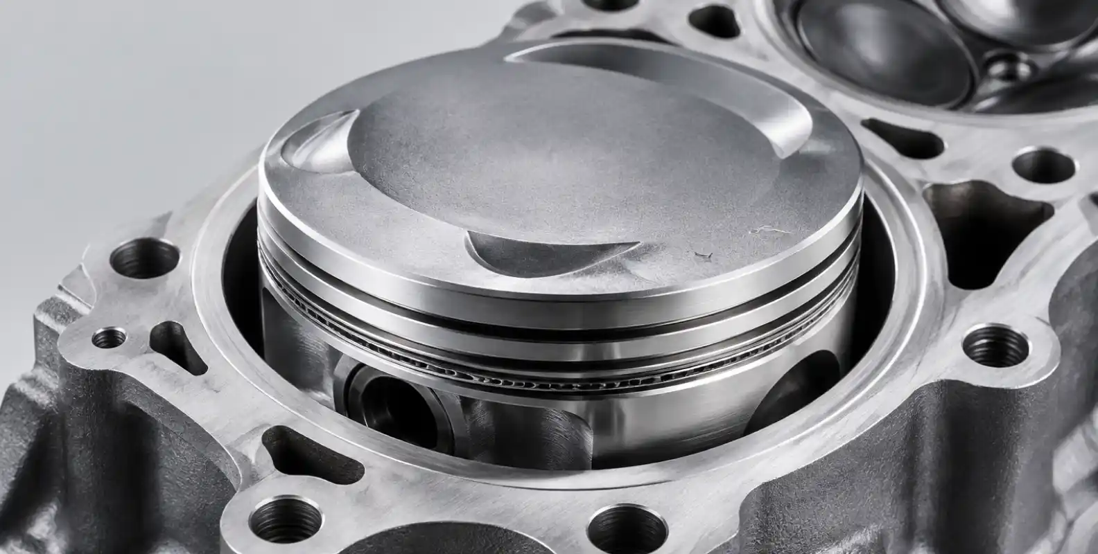
The squish band is the annular gap between piston crown and head at top dead center. As the piston rises, mixture trapped in that gap gets driven inward, and the resulting turbulence speeds up combustion and evens out the charge. Fast, even combustion is what resists knock.
Two numbers dominate. Squish clearance on a high-output four-stroke single usually runs 0.9 to 1.3 mm. Tighter gives stronger turbulence but demands tight control of piston rock and thermal growth. Squish area — the share of bore covered by the band — usually runs 30 to 50 percent. More area means more mixture motion, and also more heat loss into the head.
Chamber shape inside the band decides the rest. A compact chamber shortens flame travel, and short flame travel gives the end gas less time to auto-ignite. Two heads at identical compression ratios can behave very differently on the same fuel for exactly this reason.
Setting the ratio: fuel, elevation and the rulebook
A compression specification is only valid inside its environment. Fuel octane and air density are the two variables that move the target most, and both change between events.
| Operating condition | Recommended approach | Reason |
|---|---|---|
| Series-mandated race fuel, sea level | Target ratio at the top of the fuel’s knock margin | Fuel quality is known; use the margin you paid for |
| Pump fuel drawn at the venue | Give back ~0.5 point of ratio; add squish turbulence | Octane varies; faster combustion protects the end gas |
| Events above ~1,500 m elevation | Dedicated variant 1.0–1.5 points higher | Air density drops ~15%; cylinder pressure needs restoring |
| Endurance / rally stages over 30 min | Conservative ratio, tolerant chamber shape | Heat soak erodes knock margin late in the stage |
| Sealed production class | Machine deck to legal minimum; set volume exactly on the limit | Tech inspection measures volume, not intent |
What breaks first at elevated compression
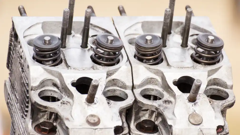
Failures at raised compression arrive in a known order, which makes inspection cheap. The spark plug complains first: a blistered or discolored ground strap reports chamber temperatures beyond the plug’s heat range. The fix is a colder plug and a mixture check, not hardware blame.
The piston crown is next. Detonation leaves a sandblasted texture at the crown edge near the squish band, then erosion, then — in terminal cases — a hole on the exhaust side. A borescope through the plug hole at top-end services catches the texture stage while the correction is still a jetting change.
In the head itself, cracks start at the valve bridge and the plug boss, the two thinnest and hottest sections. These are fatigue failures scheduled by thermal cycles. Log head hours the way you log piston hours, and retire castings on schedule rather than on symptoms.
Two-stroke heads: compression as a swappable part
Two-stroke race heads carry no ports or valves — their job is chamber shape, squish and heat rejection, while the cylinder does the breathing. The modern answer is the insert-type head: a reusable outer shell with interchangeable chamber inserts machined for different fuels, elevations or track characters.
A team can run a high-compression insert at a sea-level round on race fuel and swap to a lower-squish insert for a high-altitude round on pump gas, using hand tools between sessions. The format also isolates damage — detonation scars an insert instead of scrapping a complete head. We machine the register diameters and sealing grooves so every insert in a set measures identically, because an insert system is only as good as its interchangeability. The insert format used on our KTM aftermarket cylinder heads page follows this same logic.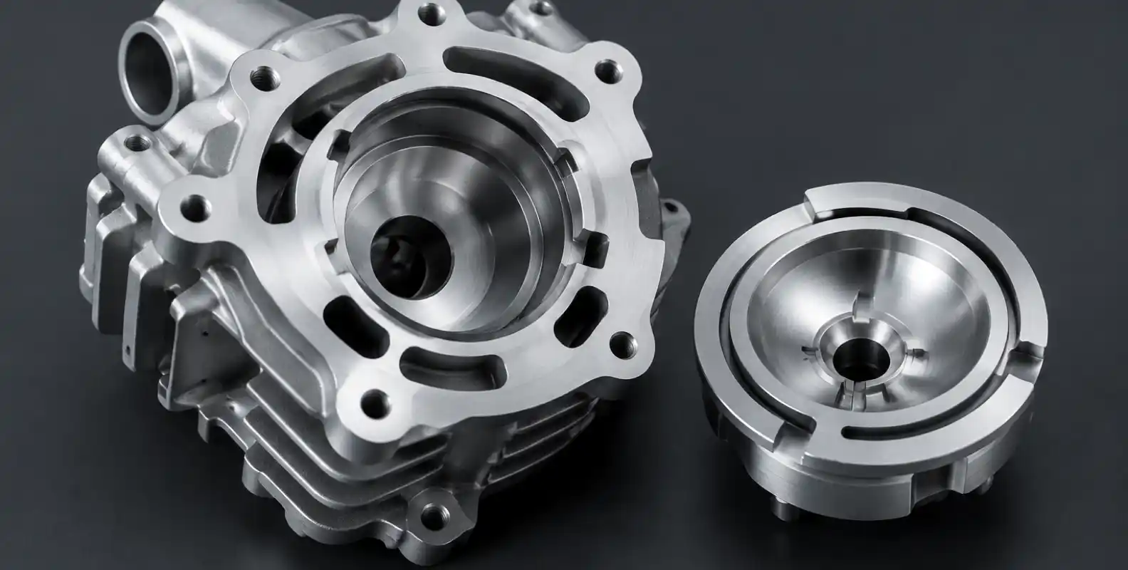
How chamber volume is controlled
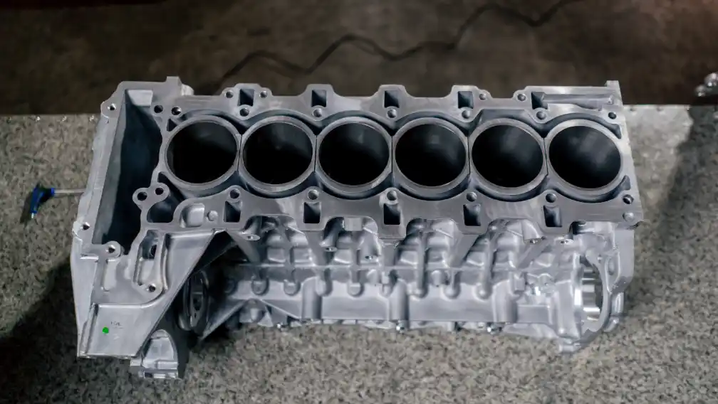
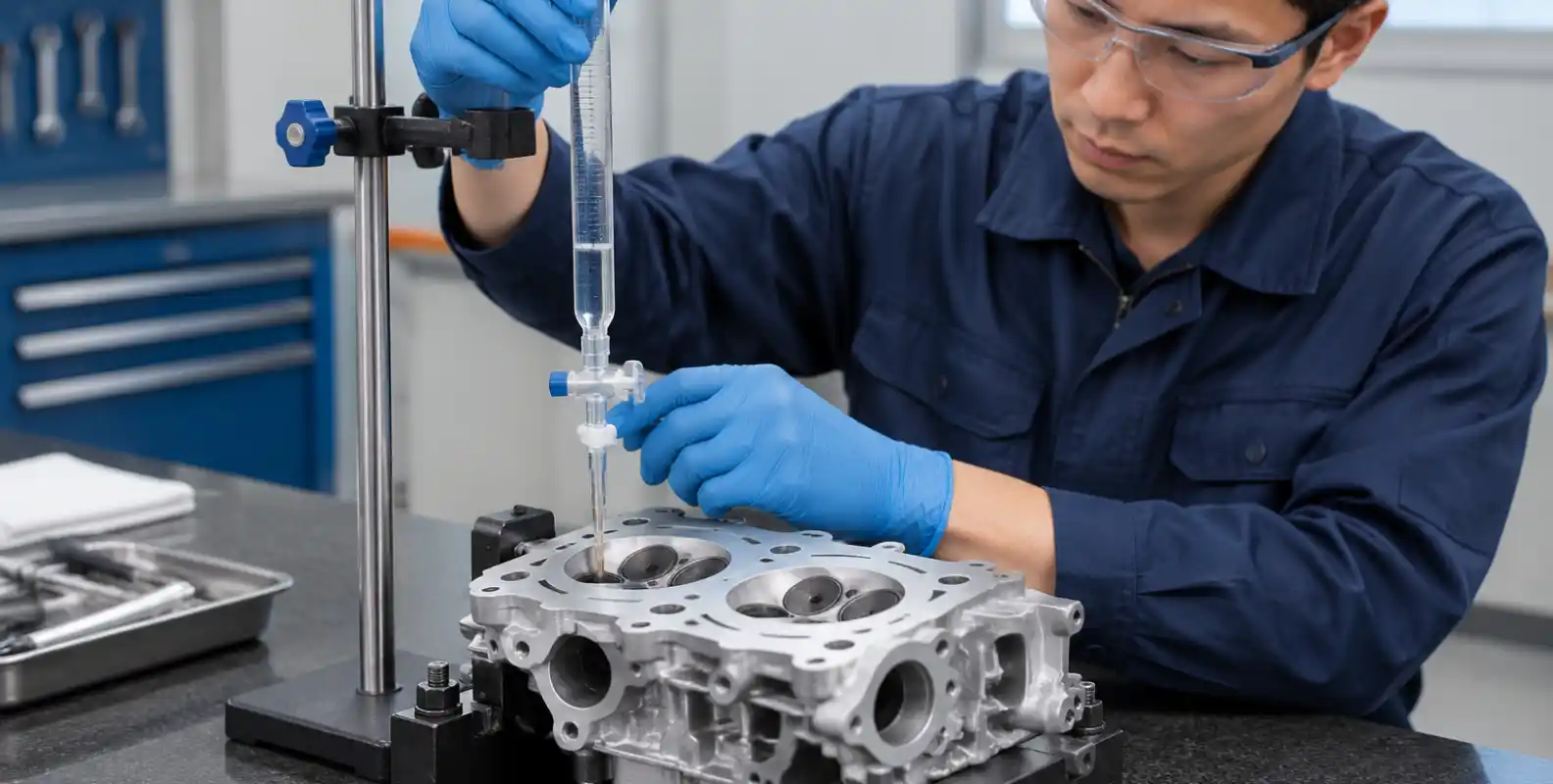
Compression ratio is set by assembled chamber volume: chamber, gasket bore, piston crown and deck clearance together. The machining is the easy part. The measurement chain is what makes the number real.
Our working procedure:
• Burette measurement of every chamber after final machining, valves and plug installed, graduated to 0.1 cc
• Acceptance window of ±0.2 cc across a matched set
• CMM check of deck flatness and chamber profile, because a flat deck is what makes cc readings repeatable
• Solder or clay squish check at assembled TDC, recorded against the head’s serial number
Each result goes into a batch record that ships with the hardware. That record answers technical inspection, guides first assembly, and defines the replacement spec if a head is damaged mid-season.
What we need to quote a compression project
A complete brief has six items: the base casting or a sample head; the piston spec including crown volume; the race gasket with its compressed thickness; the fuel actually available at your events; the class regulation text, or a statement that the build is open; and the operating window — moto length, ambient range, elevations.
The two items most often missing are gasket compressed thickness and the fuel clause. Both produce heads that are correctly machined to the wrong number. Machining-based work on an existing casting runs 15 to 25 days including documentation. Programs needing a revised casting run 45 to 60 days with tooling trials. Send the brief early in the off-season and the winter goes to dyno time instead of transit.
-

Feiya Engineering Team
A dedicated group of manufacturing experts at Feiya Machinery since 2009. With a focus on DFM (Design for Manufacturing) and quality control, our team oversees the production of 5,000+ tons of aluminum castings annually. We share practical insights on tooling, metallurgy, and machining to help global buyers make informed sourcing decisions.