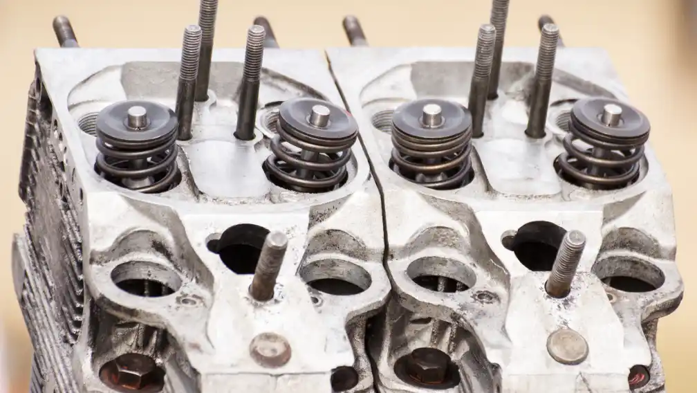
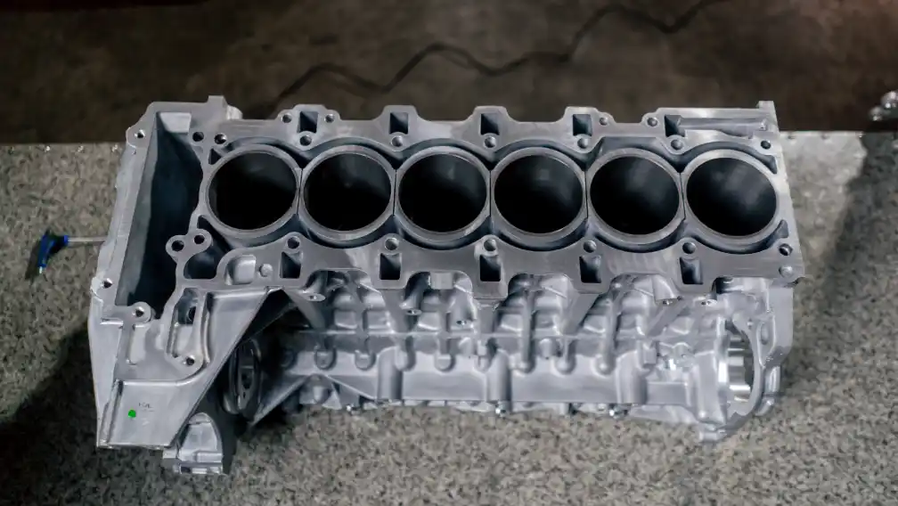
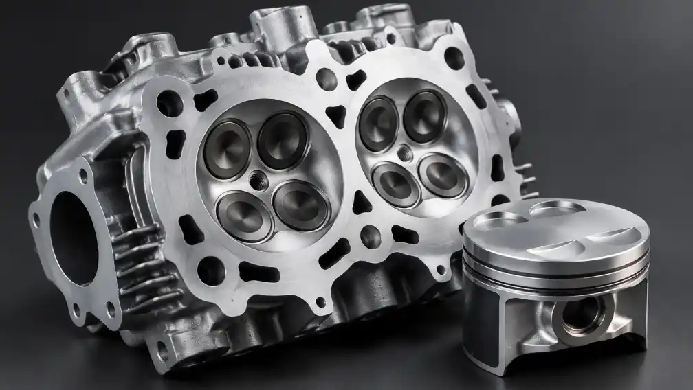
Heat is the opponent that never pits
Valves, pistons and bearings end race weekends. Temperature causes most of those failures. About a third of the fuel’s energy leaves through the cooling system, and the head carries the hottest zones in the engine: the valve bridge, the exhaust port roof, the plug boss.
The performance cost shows up before any failure. As head temperature climbs, the intake charge picks up heat on its way in, air density falls, and power fades — the engine going flat late in a moto. Knock margin erodes with temperature too, so the ignition map that was safe on lap one can detonate by lap fifteen.
The goal of thermal work is stability, not the lowest possible reading: critical zones holding a known band from first lap to last, across a cool morning practice and a forty-degree final. Stability keeps the fueling and ignition calibration valid for the full moto. Geometry — fins, jackets, wall sections — delivers that more reliably than mapping corrections.
Mapping the heat path
Heat enters the head mostly through the chamber surface and exhaust port. It leaves through coolant or cooling air, the oil circuit, conduction into the cylinder and gasket, and radiation. Change one path and the balance shifts everywhere.
The valve bridge — the material between intake and exhaust seats — is the classic hot spot in a four-stroke head and the origin of most thermal fatigue cracks. It receives heat from two seats and sheds it through whatever jacket passage or fin web the casting provides. Wall section here is a real tension: thicker conducts better but stores more thermal stress in transients.
The exhaust port runs as a heat exchanger in the wrong direction. Hot gas scrubs the walls for the full exhaust stroke, and the port roof near the short-side radius sees the highest flux. Smoothing the port cuts both carbon retention and local heat pickup. Heads that crack between exhaust seat and plug hole are reporting a failure of this thermal accounting.
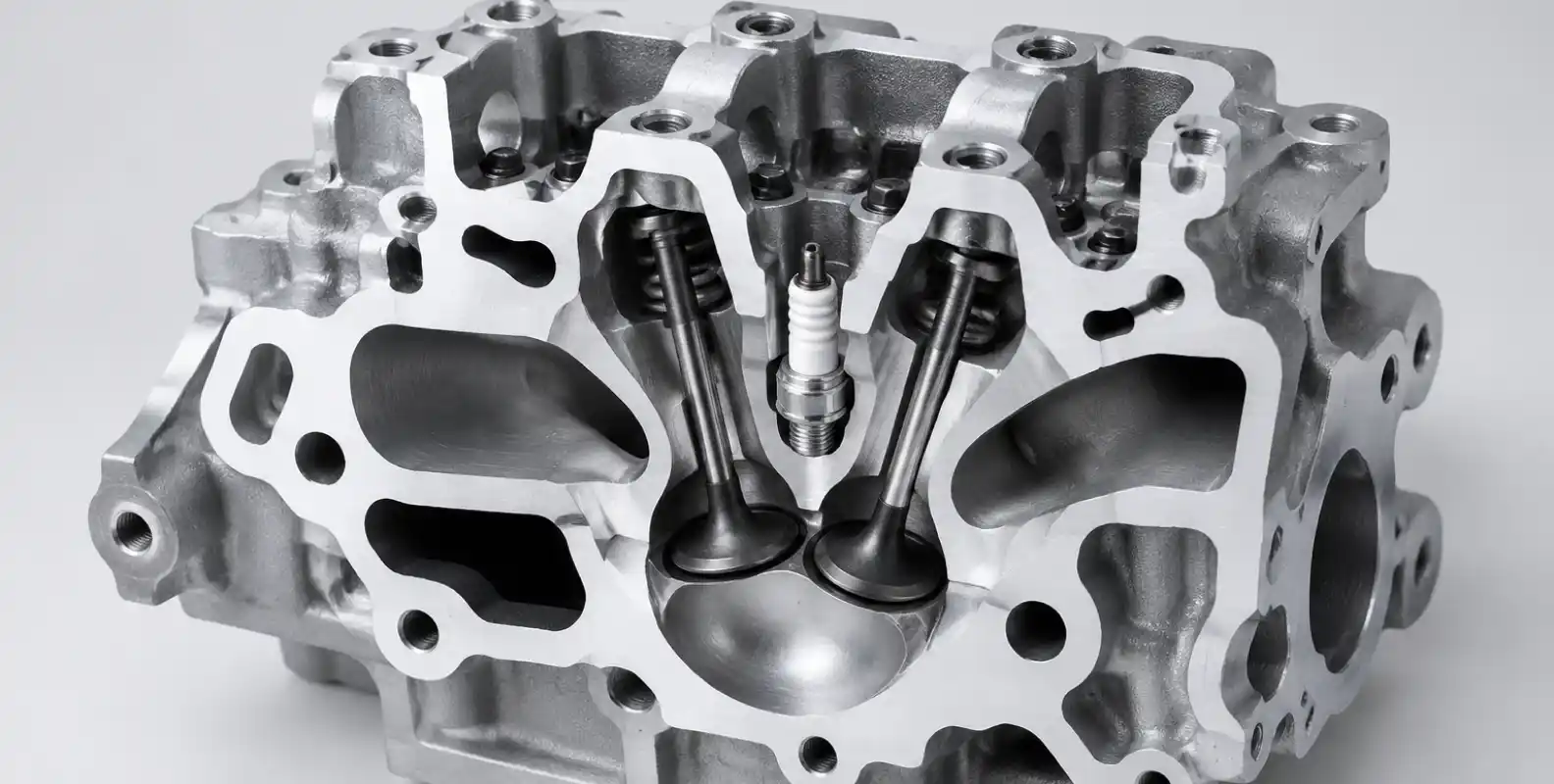
Air-cooled heads: fin design rules
Air cooling is surface area, airflow and time. Fin design maximizes the first without choking the second.
• Spacing: tall, dense fins choke the boundary layer between them. Past a spacing threshold, extra fins add weight, not cooling.
• Taper: efficient fins are thick at the root where heat enters, thin at the tip where temperature is lowest.
• Orientation: fins must follow the real airflow over the installed engine — which a fairing or skid plate can redirect completely.
• Casting quality: fins are thin sections that fill last and solidify first. Gating and venting decide whether fin roots are sound or porous, and a porous root is a crack starter next to the exhaust valve.
Vintage classes add a constraint: period appearance. Thermal improvement goes invisible — internal oil galleries added to a period casting, fin root radii improved inside the original envelope, alloy substitution where rules permit. Our work on classic motorcycle cylinder heads follows exactly this approach.
Liquid-cooled heads: the jacket you cannot see
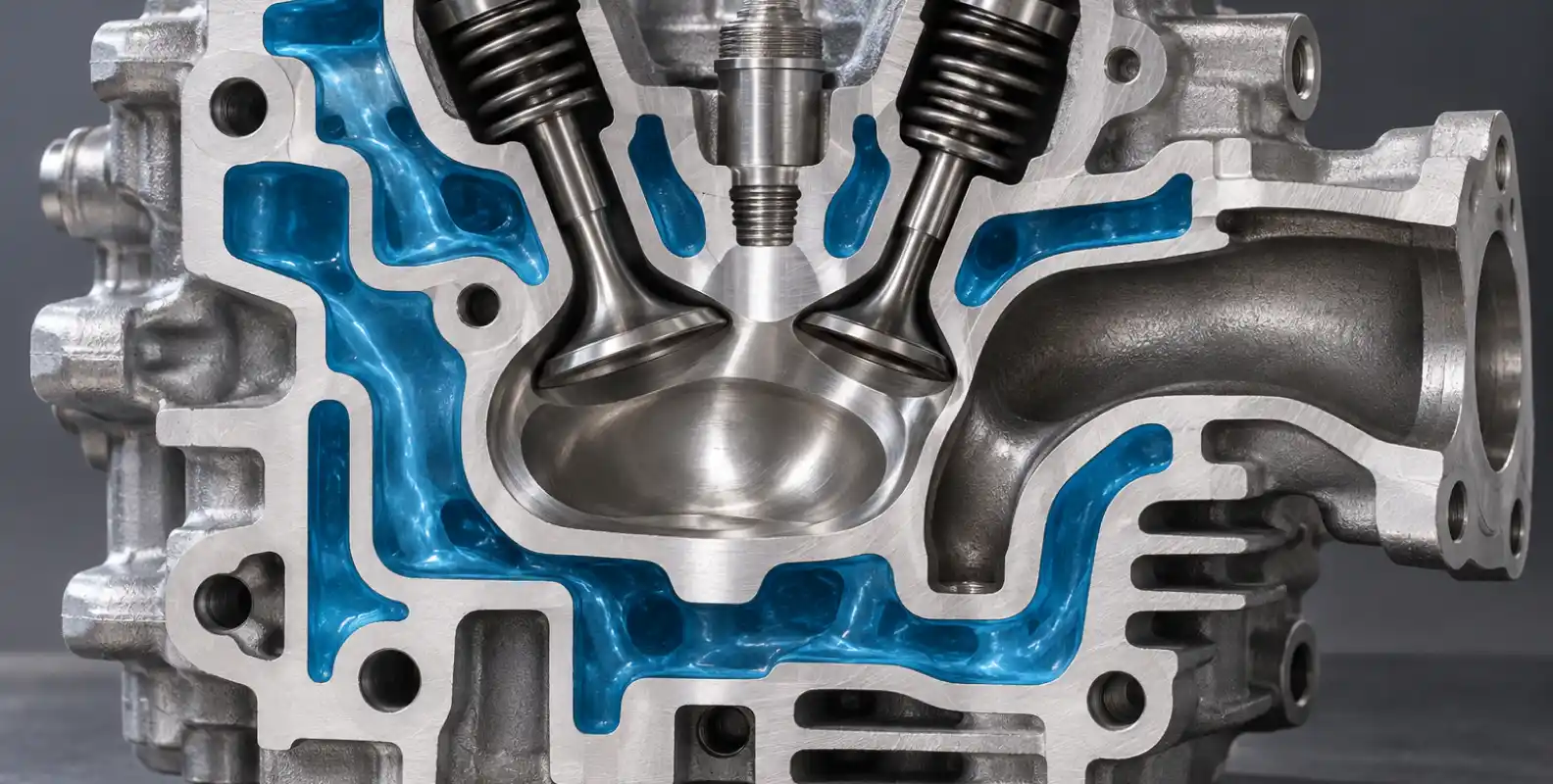
Liquid cooling moves the problem inside the casting. The jacket around a racing chamber and exhaust port runs with localized boiling at the metal surface even when healthy — nucleate boiling is normal and efficient. The design duty is keeping that boiling from turning into vapor blankets that insulate the metal.
Jacket geometry decides. Coolant velocity across the exhaust bridge and around the plug boss sweeps vapor away; dead zones are where film boiling starts. Production jackets are cored for castability first, which leaves margin. Performance castings re-core the jacket to force flow across the hot zones, and machining-based fixes — drilled cross-passages, redirected inlets — recover part of the benefit on existing castings.
Integrity is the other half. A jacket leaking into the oil circuit or the chamber ends a weekend more finally than any power shortfall. Porosity in jacket walls is the root cause, and it is decided at casting: melt cleanliness, shot parameters, venting. Every competition head we ship passes a pressure-hold test on the cooling jacket after final machining — the test that finds the porosity the eye cannot.
Building an endurance specification
Hard enduro, rally raid and desert racing stack sustained load, low vehicle speed, dust-blanked radiators and unknown fuel. The specification that survives these events follows a fixed priority: survive first, perform second, optimize third.
| Layer | Contents | What it protects |
|---|---|---|
| Survival | Verified jacket integrity, bridge cooling margin, conservative wall sections, pressure-tested assembly | Finishing the event |
| Performance | Squish set for the worst fuel on route, ratio ~0.5 point under the knock ceiling, anti-carbon chamber finish | Power over full distance |
| Optimization | Port refinement, seat angles, final flow percent | Lap time — added only where it spends no margin |
Oil as a second cooling system
On a racing engine the oil circuit is a second cooling system that reaches zones no jacket or fin can touch. Oil bathing the valve springs and cam journals carries deck heat out continuously, and gallery routing decides how much. Adding or enlarging oil passages around the exhaust side — where rules and casting sections allow — turns the oil circuit into a targeted coolant loop for the zones the jacket serves least.
One caution: wherever a drilled passage approaches a jacket wall, verify remaining thickness by measurement, never by drawing. As-cast jacket walls vary. A breakthrough between oil and water passages is found by a wall-thickness check or by the racetrack. Choose before machining.
What we measure before a head ships
Casting integrity first: spectrometer verification of melt composition, hardness confirmation of heat-treat condition, dye-penetrant inspection of chamber, port throats and fin roots.
Machining verification next: CMM measurement of chamber profile and volume, deck flatness and finish, seat concentricity. Wall thickness in the bridge, port roof and jacket boundaries gets checked against the specification drawing, because that drawing is where the thermal design lives.
Assembly tests last: pressure-hold on the cooling jacket, leak check of oil galleries, and a recorded cc of the finished chamber with valves installed. Every result enters a batch record indexed to the head’s serial number, and the record ships with the hardware. A head that arrives with its numbers asks only to be raced.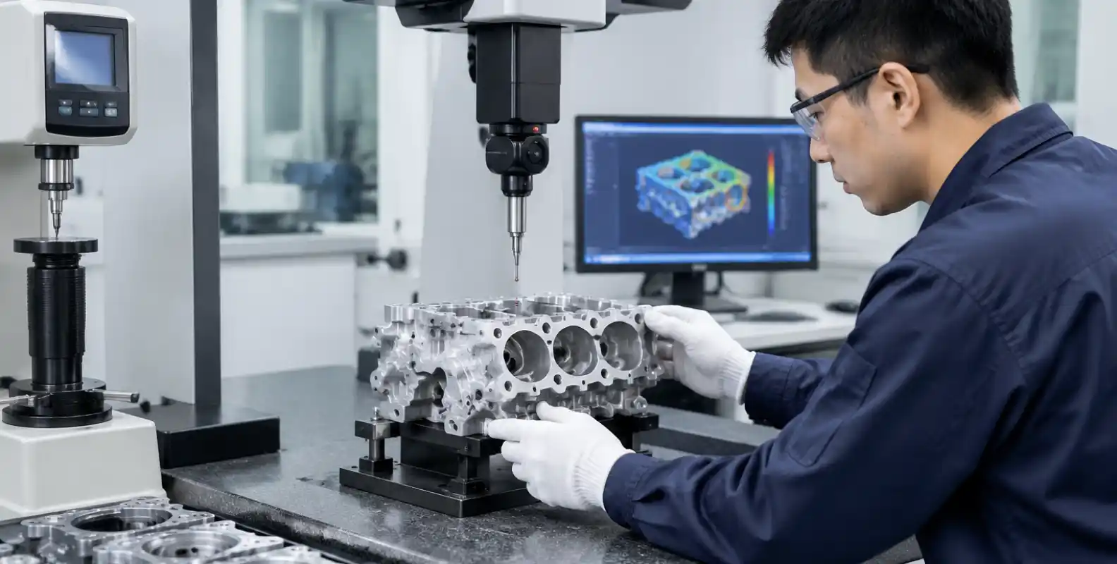
-

Feiya Engineering Team
A dedicated group of manufacturing experts at Feiya Machinery since 2009. With a focus on DFM (Design for Manufacturing) and quality control, our team oversees the production of 5,000+ tons of aluminum castings annually. We share practical insights on tooling, metallurgy, and machining to help global buyers make informed sourcing decisions.